Manipulators
A manipulator is another example of a minifactory agent, which has its own computer running its own program. Manipulators attach to the minifactory infrastructure via an agent connection. There can be many different kinds of manipulators in a minifactory. We have designed and built several manipulators of the type shown on the right in our laboratory. Minifactory manipulators have two degrees of freedom: rotation and up and down motion. When used in conjunction with the planar couriers they can jointly (but transiently) form a 4-DOF manipulator. Manipulators are used for both placing parts and for transferring subassemblies. Quick-change end effectors allow the manipulators to be easily configured to perform a variety of tasks. |
 |
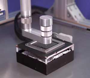 |
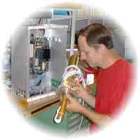
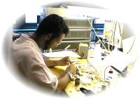
The photograph on the left shows a manipulator agent working closely with a courier agent. The two agents communicate with each other to coordinate their actions.  |

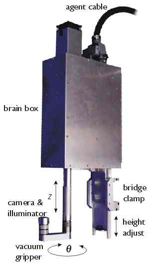
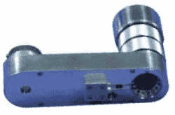
Our manipulators are designed to meet the stringent repeatability requirements and high cycle rates needed for precision assembly. The entire manipulator rotates ±270° on a pair of precision, preloaded ball bearings mounted in the base housing, which includes a 12-pole, brushless, direct-drive motor and optical encoder. The encoder gives 720,000 counts/revolution for a resolution of 1.8 arc seconds, equivalent to 0.87 microns of tangential motion at the tip of the 100 mm end effector arm. The arm can perform a 180° sweep in about 0.4 seconds. Shown below are left and right side views of one of our manipulators with its brain box cover removed to show some of the internal workings.
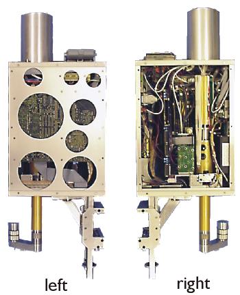
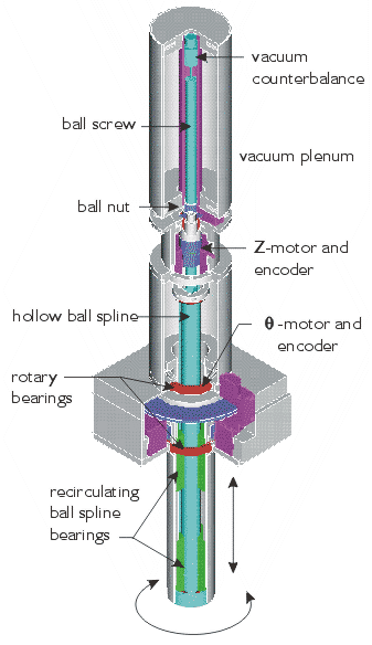
 The vertical Z motion is actuated by a ball screw attached to a hollow ball-spline shaft that couples to the end effector at its lower end. A pair of recirculating ball nuts, carried in the lower tube of the rotor assembly, guides the 120 mm Z motion with minimum friction; lateral repeatability is within a few microns from one cycle to the next. The ball-spline shaft is hollow to minimize weight and accommodate the 39 electrical conductors and 6 air/vacuum lines routed to the quick-change end effector. A rolling band of cables and hoses in the middle section of the manipulator accommodates the Z motion. A small hollow-rotor, brushless DC motor rotates the ball nut around the ball screw, driving the screw and spline-shaft vertically. Friction is low, and speeds up to 300 mm/s are achieved. An optical encoder provides vertical motion resolution of 2 microns. A vacuum-release brake prevents vertical motion when the vacuum or electrical power is off.
 A novel feature of the design is the vacuum-powered counterbalance contained in the upper unit of the manipulator assembly. A low-friction, graphite piston attached to the top of the ball screw provides a lifting force on the Z-motion assembly to minimize the load and subsequent heat dissipation experienced by the Z motor. The piston slides in a precision glass cylinder (Airpot™ actuator) which is housed inside a vacuum "plenum." A solenoid valve and pressure sensor control the "vacuum pressure" in the plenum, which is connected to the top of the air cylinder to produce the differential pressure lifting the piston. End-of-travel signals are produced by a pair of photo sensors that look through the transparent vacuum cylinder to detect the presence of the piston.
The "brain box" enclosure includes, in addition to the manipulator mechanism, a mounting clamp plus all the equipment needed for independent operation and communication. The bridge clamp provides secure mounting of the manipulator to a minifactory bridge, and allows vertical adjustment of 100 mm to accommodate different tasks. The computer, based on a 300 MHz PowerPC™ 604r processor does motion control and image processing, and communicates with the rest of the minifactory. On-board power supplies convert the 100 VDC incoming power to 5 and 12VDC for use by the computer, sensors, electronics and small actuators that may be needed in the end effector. Motor amplifiers control power to the vertical motion and rotational motion motors. An air/vacuum manifold simplifies plumbing to the grippers, brake and counterbalance, and houses the control valving and pressure sensors for these functions. A single "agent connector" provides the air/vacuum, electrical power and communication interface with the minifactory.
Modular end effectors
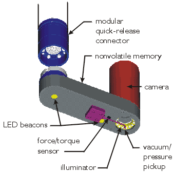 A modular quick-release connector at the lower end of the manipulator carries the electrical power and signals, and air/vacuum lines to the modular end effector. A kinematic mount consisting of a 3-ball contact and spring-loaded coupler assure repeatable attachment of the end effector. A typical end effector carries a small vacuum gripper tube mounted at a 100 mm radius from the manipulator centerline; a 2-axis force sensor integrated into the gripper; a camera and illuminator concentric with the gripper; a pair of LED "beacons" to allow optical relative-position sensing by the courier below; a non-volatile memory, and interface electronics. The memory contains a complete description of the end effector, including its full geometric model for use by other parts of the distributed minifactory system. There can be many different kinds of end effectors.
 |
 |
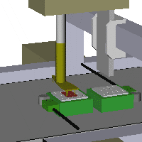 |
Since a minifactory courier's range of motion is limited by its tether, product sub-assemblies must be periodically transferred between couriers as the sub-assemblies are transported through the factory. A sub-assembly transfer end effector is "two-headed." On one side is a single vacuum gripper for grasping and placing small parts, while on the other side is a mechanism for grasping whole sub-assemblies. Thus a single manipulator can perform several very different tasks. Here is a view of such an end effector portrayed by the AAA interface tool. |
Vision-guided assembly
|
For many precision assembly tasks, vision can be used to good advantage.Shown on the left is a processed image of a part held in the vacuum gripper, and shown on the left is a processed image of the sub-assembly to which the part must be mated. These are part of a small medical device which has traditionally been assembled "by hand." |
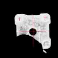
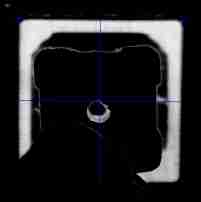

After the overhead manipulator lifts the part off the pallet, the end effector camera takes its picture. Then as a courier moves to present the sub-assembly, the vision system uses template matching to locate the top two corners of the part. After finding both corners, it calculates the center of the part given the knowledge that it happens to be symmetrical. Next, the part is lowered 1 mm above the sub-assembly and a picture is taken containing both the part and the sub-assembly. The vision system subtracts the first picture, which contains only the part, from the new picture, leaving an image of the sub-assembly behind. Next, points along the left, right, and top edges of the sub-assembly are detected. These points are processed using the Hough Transform to eliminate outliers, and linear regression is used to determine the lines representing the edges of the sub-assembly. The intersection of the lines determine the top left and right corners of the sub-assembly Finally, the vision system determines the center of the sub-assembly given the knowledge that it is symmetrical. The courier and overhead manipulator then make the appropriate adjustments to align the centers of the part and sub-assembly, after which the part is gently lowered into the sub-assembly.