Parts Feeders
Parts feeding in minifactory can be of two major types, bulk random, and organized:
Bulk random feeders such as bowl feeders
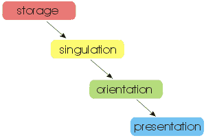
Cheap plastic molded parts and the like can be economically fed with bulk random parts feeders. The following operations must be performed: (1) a jumble of parts (all of the same type) must be stored in some sort of bin; (2) individual parts must somehow be extracted from the bin, or singulated; (3) the extracted part must be put into some standard orientation; and (4) the part must be presented to the manipulator in the position and orientation it needs. Effectively, each part's six degrees of freedom eventually become completely constrained in the bulk random feeding process.
The chief difficulty with bulk random feeders is that they are difficult to design and tend to be parts specific. In minifactory, it would be highly desirable to have bulk random parts feeders that could be rapidly reconfigured, and would also be small in size. This goal has not yet been reached, and is an important topic of our research program.
Feeders for pre-oriented parts in tubes, tapes, or trays
In contrast to bulk random feeders, for delicate and precision parts it is often better to preserve the location and orientation, i.e., constrain the freedom, of the part at its point of manufacture. This means, however, that each part must be stored in some sort of carrier such as a tube, tape, or tray. In minifactory, we are developing a tray-type precision parts feeder, discussed below.
Other considerations in the minifactory environment
 For parts feeding in minifactory, several other considerations must be taken into account. These include feeder control, part-gripper registration, and part rejection. It will generally not be necessary for bulk random feeders to be independent agents. They can operate as slaves to associated manipulators, communicating through an auxiliary i/o port. Also, feeders must present parts in a highly precise location and orientation if they are to be picked by a maipulator which does not have a centering-type gripper or vision capabilities. This can be done by incorporating a simple mechanism into the presentation portion of the bulk random feeder. Finally, if a manipulator does not like a part, or is unable to place the part in the product sub-assembly, it must be rejected. This can be facilitated by incorporating a small reject tray within the manipulator's workspace.
A gallery of parts feeders
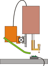
We present here several minifactory parts feeding concepts. In the sketches below, green areas indicate where the parts are stored, singulated, oriented, and/or presented. The parts themselves are indicated by small red squares. Orange areas indicate associated mechanisms. Boxes with X's represent a minifactory bridge in cross section. The product sub-assembly is shown in green, riding on the back of a courier agent. The platen is shown in gray.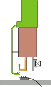 |
Small-footprint bulk randomIt is always desirable to minimize the footprint of minifactory agents. In this bulk random parts feeding arrangement, the parts feeder mechanism is located on top of its associated manipulator, and individual parts are transported to the manipulator end effector by means of a belt-like mechanism. The parts feeder is a slave to the manipulator agent. |
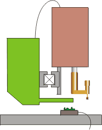
Separate bulk randomIn this bulk random parts feeding arrangement, a separate feeder mechanism is attached to the bridge opposite the manipullator. Parts are presented by a ramp- or chute-type feature. The parts feeder is a slave to the manipulator agent. |
 |
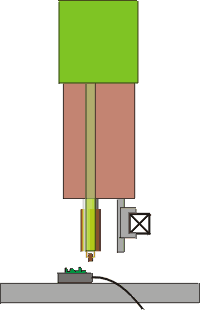 |
Direct bulk randomFor some classes of parts shapes, e.g., those with cylindrical symmetry, manipulator/feeder agents that introduce parts directly to the manipulator gripper through a hollow manipulator shaft can present effective solutions. |
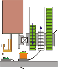
Indexed rampParts that naturally come packaged in tubes can be fed with this arrangement. A bank of tubes or ramps can be indexed or stepped sideways (in or out of the screen) by a simple mechanism whereby each step provides a new set of parts. The parts feeder is a slave to the manipulator agent. |
 |
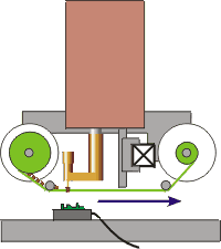 |
ReelMany parts are effectively fed in reel form, in which a number of different variations are possible. Here, parts are picked from a tape which is indexed from a supply reel to a takeup reel. The parts feeder is a slave to the manipulator agent. |
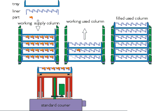
PrecisionMany "precision" or high-value parts can be packaged in arrays within trays. Here, an auxiliary courier with an elevator mechanism takes trays of parts from vertical columns or magazines and delivers them like a plate of hors d'ourves to a nearby manipulator. Spent trays are pushed back into a different column. Precision parts feeders are separate and distinct agents which must coordinate with other agents such as manipulators to carry out their operation. More details are given below. |
 |
Precision parts feeder design
In this design, the columns (magazines) are filled with trays. Each tray contains a liner which has pre-formed nests desiged to hold parts in positions on a grid in their correct orientations. The height of the trays and the number of nests are somewhat arbitrary. E.g., a tray might have one or two large nests to hold large parts or perhaps the finished product. There must be at least three columns to allow an operator sufficient time to remove filled used columns and replace them with new supply columns.
Click the graphic above to view a Flash animation of this feeder type. To closely examine the mechanisms, just right-click the window (Option-Click for Macintosh) and select "Zoom In". To return the animation to its original size, select "Show All" from the same menu. The animation loops after a while, so you'll get plenty of chances to view everything.
Some of our research in progress
Vibratory feeder with momentum cancelization
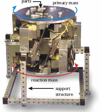
Vibr atory bowl feeders with reconfigurable gates have a lot going for them in terms of bulk parts feeding. A significant problem, however, is the vibrational pollution they create, which can seriously degrade the precision of nearby manipulators. Shown above is our attempt to reduce such vibrations to acceptable levels. Here, an electromagnetic
  drive oscillates the upper disk-shaped primary mass while also oscillating the lower reaction mass 180 degrees out of phase. Parts on the upper platform (primary mass) march around in circles in the direction shown by the blue arrow where they can be channeled into single file. Measured vibration of the support structure is attenuated by roughly a factor of 50.
Mobile vibratory feeder
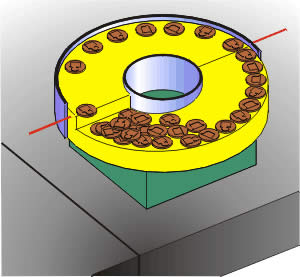 We have also been wondering if the high-performance motion capabilities of the planar motors we use in the minifactory couriers can be utilized for parts feeding. Although only capable of motion in the plane, we have demonstrated that commanding the planar motor to follow a special periodic waveform causes motion of parts resting on the motor. To use this motion capability for singulating and orienting parts, we have designed a special annular spiral feed tray that would be rigidly attached to the motor and allow for singulation and orientation of a class of parts, yielding a miniature mobile parts feeder. In this scenario, parts are placed at the bottom of the ramped section and a rotational waveform command is used to induce counter-clockwise part motion around the spiral. The ramp is steeper towards the inside edge, so that parts only climb near the outside edge of the ramp, forming a single-file line. The parts also speed up and spread out after transitioning from the ramp to the flat pickup area. An overhead vision system can then identify the singulated parts that are in the correct orientation and an overhead robot can pick them for assembly. Parts incorrectly oriented continue around the annulus and are randomly reoriented as they return to the bottom of the ramp. Although we have not yet constructed a prototype, the basic operating principles have been verified through simulation.
 ![]()
After the overhead manipulator lifts the part off the pallet, the end effector camera takes its picture. Then as a courier moves to present the sub-assembly, the vision system uses template matching to locate the top two corners of the part. After finding both corners, it calculates the center of the part given the knowledge that it happens to be symmetrical. Next, the part is lowered 1 mm above the sub-assembly and a picture is taken containing both the part and the sub-assembly. The vision system subtracts the first picture, which contains only the part, from the new picture, leaving an image of the sub-assembly behind. Next, points along the left, right, and top edges of the sub-assembly are detected. These points are processed using the Hough Transform to eliminate outliers, and linear regression is used to determine the lines representing the edges of the sub-assembly. The intersection of the lines determine the top left and right corners of the sub-assembly Finally, the vision system determines the center of the sub-assembly given the knowledge that it is symmetrical. The courier and overhead manipulator then make the appropriate adjustments to align the centers of the part and sub-assembly, after which the part is gently lowered into the sub-assembly.